pipe pressure testing standards pdf
Pipe pressure testing standards ensure safety and reliability in piping systems. Key codes like ASME B31.3 and Section VIII outline hydrostatic and pneumatic test procedures. A free PDF guide provides essential compliance details and safety protocols for engineers and technicians, ensuring system integrity and operational readiness.
1.1 Importance of Pressure Testing in Piping Systems
Pressure testing is critical for ensuring the integrity and safety of piping systems. It validates the design, materials, and fabrication by identifying potential defects or weaknesses. This process ensures compliance with codes like ASME B31.3 and Section VIII, guaranteeing system reliability. Hydrostatic and pneumatic tests are essential for verifying the maximum allowable working pressure (MAWP) and preventing failures during operation. Proper testing protocols minimize risks, ensuring the system operates safely under designated conditions. A comprehensive guide, such as a pipe pressure testing standards PDF, provides detailed procedures and safety measures, helping engineers and technicians maintain compliance and operational readiness.
1.2 Overview of Key Standards and Codes
Key standards for pipe pressure testing include ASME B31.3, ASME Section VIII, and UG-99, UG-100, and UG-101 guidelines. These codes provide detailed procedures for hydrostatic and pneumatic testing, ensuring system safety and compliance. ASME B31.3 focuses on process piping, while Section VIII addresses pressure vessels. UG-99 outlines hydrostatic test requirements, UG-100 covers pneumatic tests, and UG-101 establishes maximum allowable working pressure (MAWP). These standards are part of American National Standards, ensuring uniformity and reliability. They specify test pressures, safety protocols, and acceptance criteria, helping engineers and technicians maintain compliance. A pipe pressure testing standards PDF offers a comprehensive guide to these codes, simplifying implementation and ensuring operational readiness.
ASME B31.3 Piping Code Requirements
ASME B31.3 applies to process piping and tubing systems, ensuring design, material, and testing compliance. It covers safety, reliability, and operational standards for piping installations.
2.1 Scope and Application of ASME B31.3
ASME B31.3 applies to process piping and tubing systems, including those in chemical plants, oil refineries, and related industries. It governs the design, materials, fabrication, and testing of piping components to ensure safety and reliability. The code is specifically tailored for piping systems that operate at elevated temperatures and pressures, requiring precise engineering and compliance. It does not cover boiler or pressure vessel piping, which fall under other ASME sections. Users of this code must adhere to its guidelines to ensure system integrity and operational safety. Proper application of ASME B31.3 is critical for maintaining compliance and preventing failures in high-risk environments.
2.2 Design, Materials, and Fabrication Standards
ASME B31.3 specifies rigorous design, material, and fabrication standards to ensure piping system integrity. Design calculations must account for pressure, temperature, and corrosion allowances. Materials must comply with ASME standards, with traceability and certification required. Fabrication processes, including welding and bending, must adhere to code-specific procedures. Non-destructive examination (NDE) is mandatory for critical joints. All components must meet minimum design and material requirements to ensure safe operation. Proper documentation of design, material selection, and fabrication steps is essential for compliance. These standards collectively ensure that piping systems are durable, safe, and capable of withstanding operational stresses. Adherence to these guidelines is critical for maintaining system reliability and preventing failures.
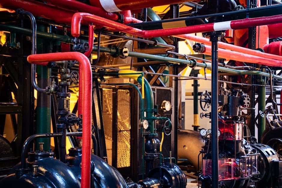
Hydrostatic Testing Procedures
Hydrostatic testing involves filling piping systems with water to verify integrity. ASME standards specify test pressures, safety protocols, and procedures to ensure system reliability and compliance.
3.1 Test Pressure Calculation and Requirements
Accurate test pressure calculation is critical for ensuring piping system integrity. ASME standards, such as B31.3 and Section VIII, provide detailed formulas and guidelines for determining test pressures. Factors like design pressure, temperature, and safety margins are considered to ensure safe testing. Hydrostatic test pressures are typically 1.5 times the design pressure, while pneumatic tests may vary based on system specifics. Compliance with these requirements ensures the system can withstand operational stresses without failure. Proper documentation and adherence to safety protocols are essential to validate test results and maintain system reliability.
3.2 Safety Protocols During Hydrostatic Testing
Safety protocols during hydrostatic testing are paramount to prevent accidents and ensure system integrity. Isolate the test area and ensure all valves are properly positioned. Use test pumps with safety features, such as pressure relief valves, to prevent over-pressurization. Personnel should wear protective gear, including hard hats and safety glasses. Continuous monitoring of pressure gauges and visual inspections for leaks or deformities are essential. Emergency shutdown procedures must be in place, including a means to quickly depressurize the system if anomalies are detected. Compliance with ASME standards ensures adherence to proven safety practices, minimizing risks to personnel and equipment. Proper documentation of safety measures is also required for audit and compliance purposes.
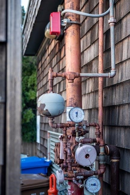
Pneumatic Testing Guidelines
Pneumatic testing guidelines outline procedures for using air or gas to test piping systems. They differ from hydrostatic tests, emphasizing safety and pressure control. ASME standards provide detailed protocols for pressure levels, duration, and safety precautions to ensure system integrity and compliance. Proper safety measures, such as venting and emergency shutdowns, are critical to prevent accidents during testing.
4.1 Differences Between Pneumatic and Hydrostatic Tests
Pneumatic and hydrostatic tests differ in the medium used: water for hydrostatic and air or gas for pneumatic. Hydrostatic tests typically use higher pressures and are safer due to water’s incompressibility, while pneumatic tests are lighter but riskier due to the compressibility of air. Safety protocols for pneumatic tests are stricter, requiring lower pressures and emergency shutdowns. Hydrostatic tests are preferred for higher pressure systems, while pneumatic tests are used for lower pressure or when water contamination is a concern. Both methods ensure system integrity but vary in application, safety measures, and suitability based on system requirements and environmental factors. Proper selection and execution are critical for compliance and safety.
4.2 Pressure and Time Diagrams for Pneumatic Tests
Pressure and time diagrams are essential for pneumatic testing, outlining the relationship between pressure levels and test duration. These diagrams ensure tests are conducted safely and efficiently, adhering to ASME standards. They specify the gradual increase of pressure, holding periods, and steps to verify system integrity. Safety protocols are emphasized, including emergency shutdowns and pressure relief mechanisms. The diagrams also guide the identification of leaks or weaknesses during testing. Proper interpretation of these diagrams ensures compliance with codes and guarantees system reliability. They are tailored to specific system requirements, ensuring accurate and consistent test results. Detailed pressure-time graphs help technicians monitor progress and maintain safety throughout the testing process.
ASME Section VIII, Division 1 Requirements
ASME Section VIII, Division 1 specifies requirements for pressure vessels, including UG-99 hydrostatic tests, UG-100 pneumatic tests, and UG-101 proof tests to establish MAWP.
5.1 UG-99 Hydrostatic Pressure Test Requirements
UG-99 outlines hydrostatic test requirements for pressure vessels to ensure structural integrity. The test involves filling the vessel with water and pressurizing it to a specified level, typically 1.5 times the maximum allowable working pressure (MAWP). This procedure verifies that the vessel can withstand design pressures without leakage or deformation. Compliance with UG-99 ensures safety and reliability, meeting ASME standards. The test medium, duration, and acceptance criteria are clearly defined to guarantee consistency and accuracy. Proper documentation and certification are required to validate the test results, ensuring adherence to regulatory and industry standards.
5.2 UG-100 Pneumatic Test Procedures
UG-100 pneumatic test procedures, outlined in ASME Section VIII, Division 1, provide guidelines for testing pressure vessels using gas as the test medium. Unlike hydrostatic tests, pneumatic tests use compressed air or inert gas, typically at a lower pressure but with higher stored energy, requiring strict safety protocols. The test involves pressurizing the vessel to a specified level, often lower than hydrostatic pressures, and monitoring for leaks or deformations. Pressure and time diagrams are essential for documenting the test process. Safety measures, such as controlled test environments and emergency shutdown procedures, are critical due to the risks associated with gas testing. Compliance with UG-100 ensures the vessel’s structural integrity and operational safety, adhering to ASME standards for design and construction. Proper documentation and certification are required to validate test results.
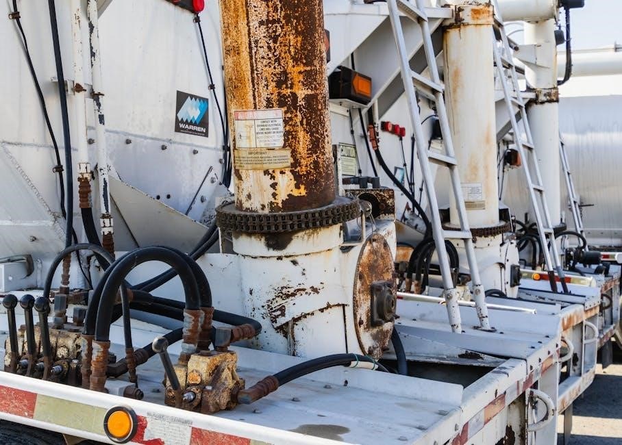
Proof Tests for Maximum Allowable Working Pressure
Proof tests, such as UG-101, determine the maximum allowable working pressure (MAWP) by applying controlled pressure and monitoring for structural integrity and safety compliance with ASME standards.
6.1 UG-101 Proof Test Requirements
The UG-101 proof test is a critical procedure under ASME Section VIII, Division 1, used to establish the maximum allowable working pressure (MAWP) when design calculations are unavailable. This test involves applying a controlled pressure higher than the expected MAWP to ensure the component’s structural integrity. The test pressure must be carefully calculated and monitored to avoid damage. Safety precautions are essential, as the test involves high risks. The component is inspected for leaks, deformations, or other defects during and after the test. Documentation of the test results is mandatory, and the data must be reviewed by authorized personnel to confirm compliance with ASME standards. This ensures the component’s reliability and safety for operational conditions.
6.2 Establishing MAWP Through Testing
Maximum Allowable Working Pressure (MAWP) is determined through rigorous testing procedures outlined in ASME standards. Hydrostatic and pneumatic tests are commonly used to validate design pressures. The UG-101 proof test is a key method, where components are subjected to elevated pressures to ensure they meet safety and performance criteria. Test results are analyzed to confirm the component’s ability to withstand operational stresses without failure. Documentation of test pressures, durations, and outcomes is critical for certification. Compliance with ASME Section VIII requirements ensures the MAWP is accurately established, guaranteeing the component’s reliability under normal operating conditions. These tests are essential for verifying design integrity and ensuring long-term safety in industrial applications.
Leak Testing Requirements
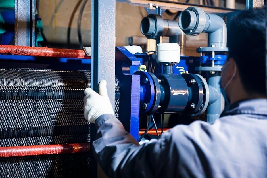
Leak testing ensures piping systems are free from defects and meet safety standards. ASME B31.3 outlines methods like hydrostatic and pneumatic tests to verify system integrity and compliance.
7.1 Alternative Methods for Leak Detection
Alternative leak detection methods offer flexible solutions for ensuring piping system integrity. Ultrasonic testing and acoustic emission monitoring are non-invasive techniques that detect leaks without dismantling systems. Infrared imaging identifies temperature anomalies, indicating potential leaks. These methods complement traditional hydrostatic and pneumatic tests, providing real-time data and reducing downtime. ASME standards allow these alternatives under specific conditions, ensuring compliance while enhancing efficiency. Proper training and equipment are essential for accurate results. These innovative approaches are particularly useful in sensitive or hard-to-reach areas, minimizing risks and optimizing system performance. By integrating advanced technologies, engineers can ensure safer and more reliable piping systems, meeting modern industry demands for precision and safety.
7.2 Compliance Procedures for Leak Testing
Compliance with leak testing procedures ensures piping systems meet safety and performance standards. ASME B31.3 and Section VIII provide detailed guidelines for test pressures, durations, and acceptance criteria. Testing must be conducted by qualified personnel using approved methods and equipment. Documentation of test results is critical, including records of pressure levels, test mediums, and any anomalies detected. Post-test inspections verify system integrity, and all findings must be reviewed and approved by authorized personnel. Compliance also involves maintaining detailed reports for certification purposes, ensuring traceability and accountability. Adherence to these procedures minimizes risks, guarantees operational safety, and aligns with regulatory requirements, making it a cornerstone of piping system validation.

Pressure and Leakage Test Specifications
Pressure and leakage tests ensure piping systems meet design and safety standards. Specifications outline test procedures, acceptance criteria, and compliance requirements, ensuring system integrity and operational safety.
8.1 Scope of Work for Pressure and Leakage Tests
The scope of work for pressure and leakage tests involves verifying the integrity of piping systems, including pipes, valves, and fittings. Tests are conducted to ensure compliance with design specifications and safety standards. All components installed under the contract must undergo testing to validate their performance under operational conditions. The process includes applying the specified test pressure, monitoring for leaks, and documenting results. Detailed procedures and acceptance criteria are outlined in the project standards to ensure consistency and accuracy. The tests are critical for identifying potential defects or weaknesses, ensuring the system’s reliability and safety before commissioning. Proper documentation and certification are required to confirm compliance with applicable codes and regulations.
8.2 Test Procedures and Acceptance Criteria
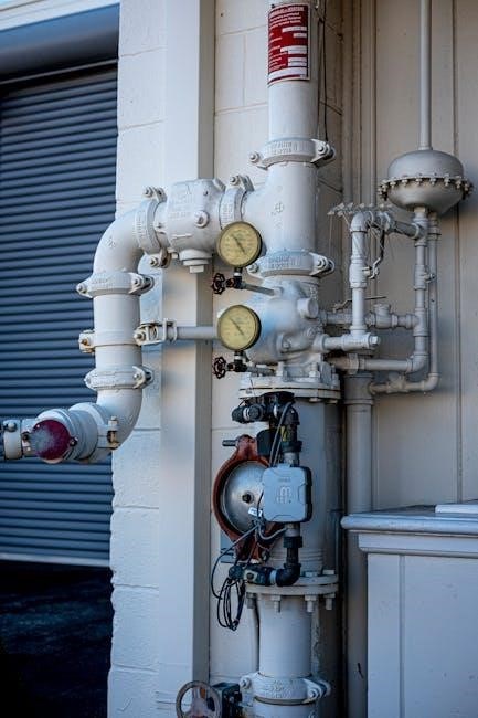
Test procedures for pressure and leakage tests are meticulously detailed to ensure accuracy and safety. The process involves applying the specified test pressure, monitoring the system for leaks, and recording data. Acceptance criteria include achieving the required pressure without exceeding allowable stress limits and ensuring no visible leaks or excessive leakage rates. Documentation of test results is mandatory, with clear pass/fail criteria outlined in the standards. Compliance with codes like ASME B31.3 and Section VIII is verified through these procedures. Any deviations from the expected results require corrective action before system approval; Proper test execution and documentation ensure the piping system meets design and safety requirements, guaranteeing operational reliability and compliance with regulatory standards.
Safety Measures and Precautions
Safety protocols during pressure testing include proper equipment setup, emergency preparedness, and adherence to ASME standards. Ensuring a safe environment minimizes risks and prevents accidents.
9.1 Safe Pressure Testing Practices
Safe pressure testing practices are critical to ensuring the integrity of piping systems. Always follow established SOPs and ASME standards for hydrostatic or pneumatic tests. Isolate the system under test, and ensure all safety valves and equipment are in place. Use appropriate personal protective equipment and monitor pressure levels closely. Never exceed the maximum allowable working pressure (MAWP) during testing. Properly vent the system before and after testing to prevent pressure buildup. Maintain clear communication among the test team and have an emergency response plan ready. Adherence to these practices minimizes risks and ensures compliance with safety regulations, protecting both personnel and equipment during the testing process.

9;2 Emergency Procedures During Testing
Emergency procedures during pressure testing are essential to mitigate risks. In case of unexpected pressure drops, leaks, or system failures, immediately isolate the test area and depressurize safely. Evacuate personnel and ensure all safety valves activate properly. Document the incident and conduct a thorough investigation to identify root causes. Communicate clearly with the test team and follow established emergency response plans. Always have a first aid kit and fire extinguisher on site. Post-test inspections are critical to assess system integrity before resuming operations. Adherence to these protocols ensures personnel safety and minimizes potential damage to equipment. Regular training on emergency procedures is vital for preparedness and compliance with ASME standards and safety regulations.
Documentation and Certification
Accurate documentation of test results is crucial for compliance. Detailed records, including pressure readings and leak detection data, must be maintained. Certification ensures adherence to ASME standards, validating system safety and integrity for operational approval.
10.1 Record-Keeping for Test Results
Maintaining detailed records of pressure and leakage tests is essential for compliance and system integrity. Test results, including pressure readings, durations, and any anomalies, must be accurately documented. Records should include dates, test procedures followed, and the personnel involved. Digital or physical storage methods should ensure data integrity and accessibility. Compliance with ASME standards requires retaining these records for audits and future reference. Proper documentation also supports traceability and verification of system performance. Additionally, records provide a historical overview of the piping system’s condition, aiding in maintenance planning and operational safety. Adherence to these practices ensures accountability and reliability in piping systems.
10.2 Certification Requirements for Compliance
Certification is critical to ensure piping systems meet safety and regulatory standards. Test results must be reviewed and certified by qualified personnel, adhering to ASME guidelines. Certificates should include test details, such as pressure levels, durations, and acceptance criteria. Third-party inspections may be required to verify compliance, especially for high-risk systems. Proper certification ensures accountability and confirms that the piping system is safe for operation. Non-compliance can lead to legal and operational risks. Therefore, maintaining accurate and validated certification records is essential for audits and long-term system reliability; Certification also provides traceability, ensuring all tests align with industry standards and project specifications.

